Overview
Dual-Channel CAN FD Interface
Product Features
CAN0 and CAN1 transmit and receive independently, suitable for dual bus joint debugging, pair-to-pull testing, gateway verification and production line parallel testing.
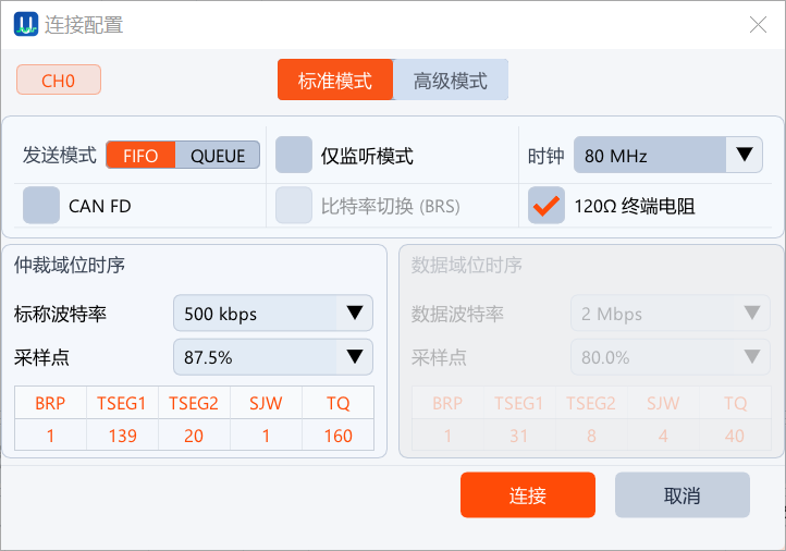
Covers CAN FD, BRS, high throughput and 64-byte payloads for traditional CAN and CAN FD debugging.
LM mode can be registered as can0/can1 via the UCAN LM SocketCAN driver, directly using candump, cansend and existing Linux CAN applications.
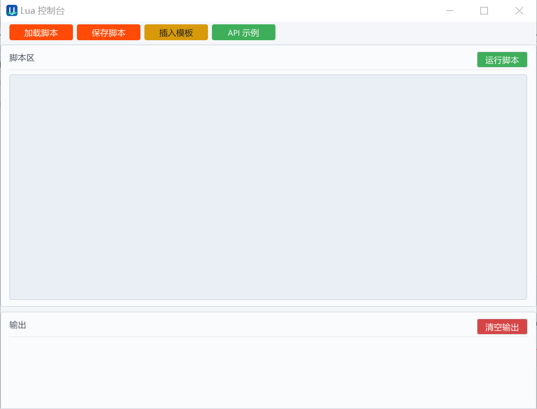
provides PyUSB CLI and API, suitable for automated testing, production test scripts, device information reading, terminal resistance control and fault diagnosis.
configures a one-shot sending slot through the device timestamp. The host sends it in advance, and the device outputs CAN/CAN FD frames according to the PTPC time point.
The button switches the terminal resistor, the status light shows the running status, and the closed-source UCAN-Analyzer desktop application provides firmware update.
Three uses of LM protocol
driver
script
integration
Working form
can-utils
Existing CAN application
dual channel CAN FD
timestamp / reservation to send
driver
sensor/gateway
Robot body communication and debugging
is suitable for dual-channel communication debugging of robot joint modules, end effectors, sensors, I/O boards and power management units.
Supports motor driver parameter configuration, status reading, control message verification and exception frame capture, reducing single-joint commissioning time.
monitors the bus load, error status, message cycle and key ID distribution during the robot complete stage, helping to locate wire harness, terminal, bit rate and node abnormalities.
combines Python scripts and scheduled sending to construct periodic control frames, fault injection, long-term stress testing and production line communication checks.
debugging script / test platform
packet capture / send / scheduled send
sensor
terminal and I/O module
Multi-platform host computer
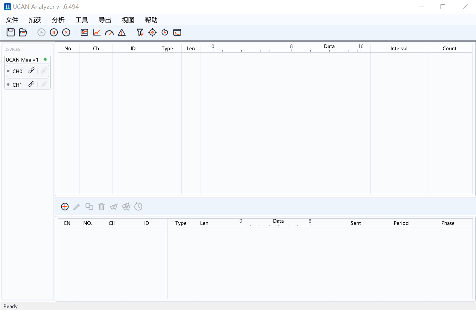
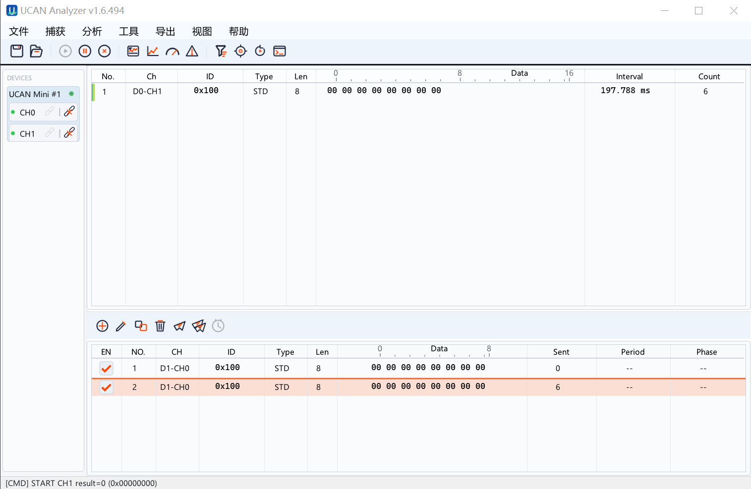
UCAN-Analyzer is the companion desktop analysis tool for UCAN-Mini, covering CAN/CAN FD device configuration, transmit/receive testing, and bus analysis.
The release list covers Windows x86_64, Linux x86_64 and macOS ARM64, which is suitable for R&D, testing and field engineers using different host environments.
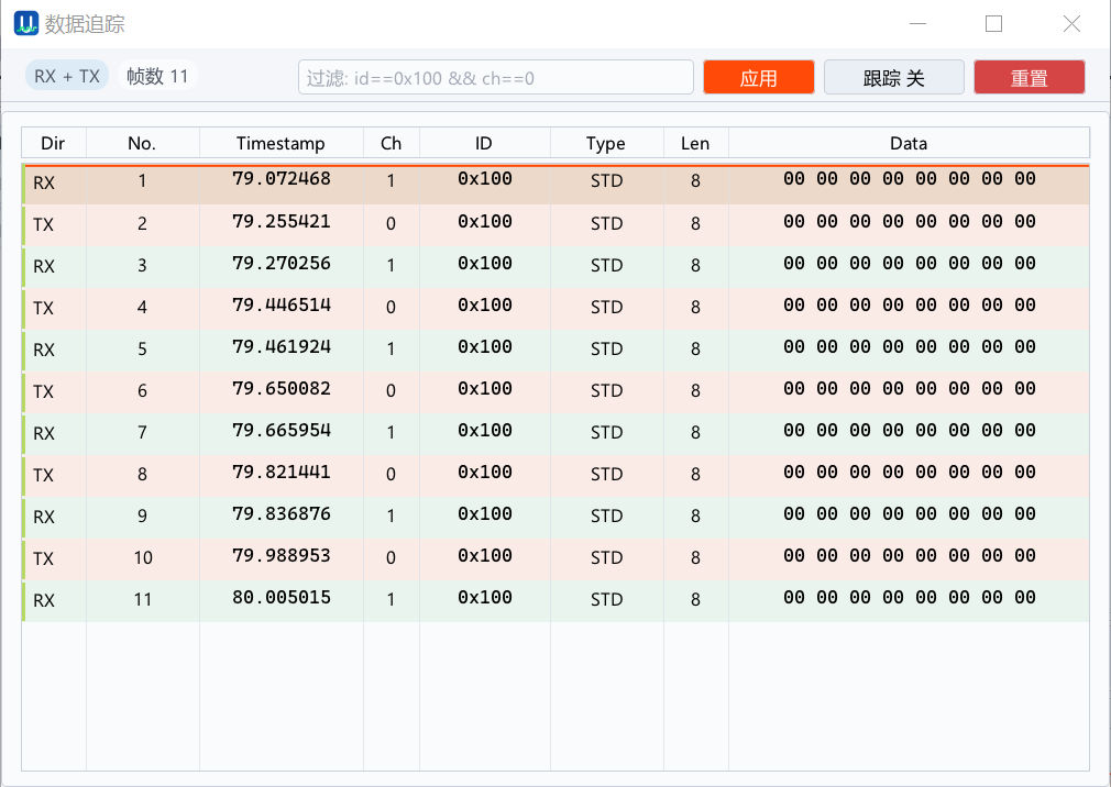
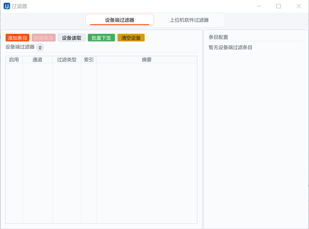
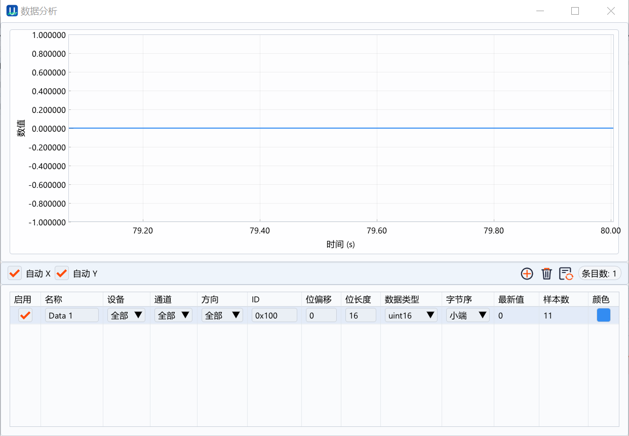
supports real-time frame monitoring, filtering, tracing, bus load, error statistics, data analysis entries and scalable waveform viewing.
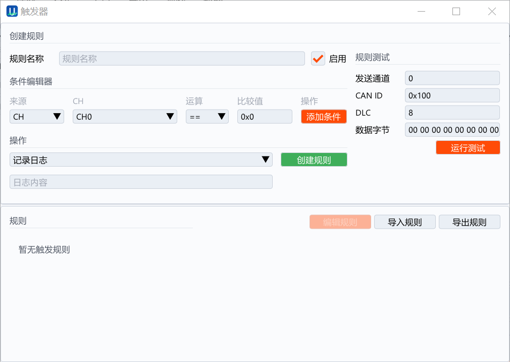
supports send editing, batch/periodic sending, DBC parsing, signal curves, trigger rules and firmware updates.
Application scenarios
| Scenario | Recommended usage | Product value |
|---|---|---|
| Robot body communication debugging | UCAN-Analyzer + LM protocol | Monitor CAN FD messages of joints, sensors, I/O and power modules |
| Robot production line communication inspection | Python CLI / API | Automatic configuration, sending and receiving, scheduled sending and status report collection |
| Linux CAN application migration | LM kernel driver | The device registers as a SocketCAN interface, with limited changes to the client program |
| Automated testing and production testing | Python CLI / API | Scripts can complete configuration, sending and receiving, status query, appointment sending and report collection |
| CAN FD R&D joint debugging | LM protocol or SocketCAN | Dual channels, BRS, timestamps and error status facilitate problem location |
| Periodic control or trigger test | Scheduled transmission | The host delivers in advance, and the device sends according to the local time point, reducing the impact of PC scheduling jitter |
| Field maintenance | UCAN-Analyzer + status light | Closed-source desktop firmware update, fault prompts and terminal resistor switching on the same device |
Specification summary
| Category | Summary |
|---|---|
| Product form | USB to dual-channel CAN/CAN FD interface |
| Main protocol | LM protocol |
| Linux support | UCAN LM out-of-tree SocketCAN kernel driver |
| Python support | ucan_mini_cli.py and ucan_mini_proto.py |
| PC tool | UCAN-Analyzer, supports configuration, transceiver, filtering, tracking, analysis, waveform and firmware update |
| Host computer platform | Windows x86_64, Linux x86_64, macOS ARM64 |
| LM VID/PID | 0x34B7 / 0xE471 |
| CAN channel | 2-way CAN/CAN FD |
| Maintenance capability | Closed-source UCAN-Analyzer firmware update, terminal resistance control, status light diagnosis |